
I’ve developed an auxiliary lithium-battery system for my vehicle that powers the vehicle’s electrical system when the engine is off and automatically recharges when the engine is running (via alternator). This allows accessories to be powered for an extended period while the vehicle is at rest. Use cases include charging my laptop and phone while somewhere like a campsite, as well as environmental data collection (BirdNET-Pi). Also I can use my portable air compressor to fill tires without starting the engine.
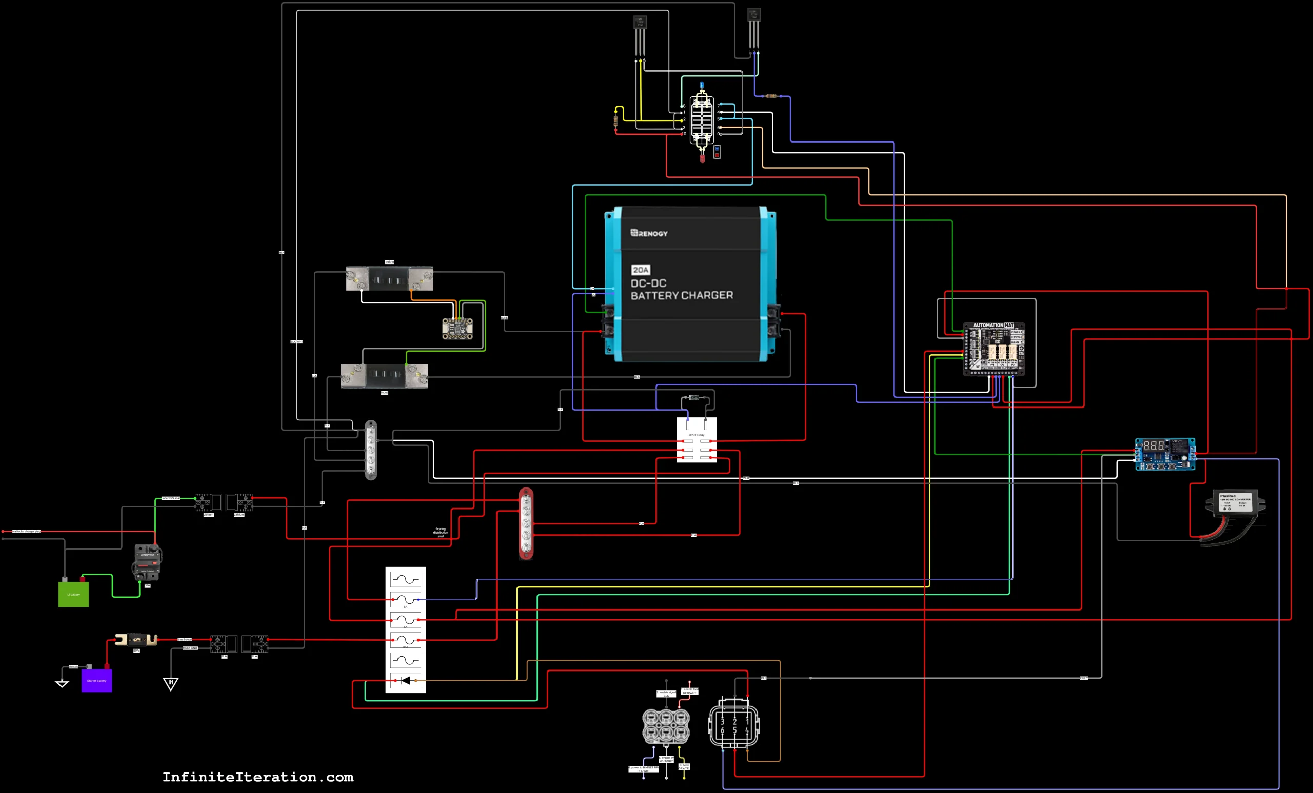
The vehicle’s starter battery and the lithium battery must be isolated to prevent the starter pulling current from the lithium battery while starting and to prevent the alternator from pushing too much current into the lithium battery while running. Also, the lithium battery must be allowed to discharge more deeply – to a lower voltage – than the starter battery will tolerate. I am using a DC/DC charger to accomplish this. Charge direction is switched using a DPDT relay. Charge current is monitored by two low-side current shunts – one on each “side” of the charger input side – paired with a 16-bit ADC.
The system is controlled by a Raspberry Pi 4B with a PimoroniHAT’s relays to provide se Automation HAT. It automatically infers vehicle operating state and directs battery charging accordingly.
The Raspberry Pi (RPi) must turn on and off automatically and have the ability to turn itself off (while still turning on automatically next cycle). To allow this, its 12V->5V DC converter is powered by a delay-on-release relay, triggered off the ignition’s ACC signal. When the signal is removed, the RPi decides based on vehicle operating state whether to turn itself off during the countdown or stay on, in which case, the RPi will close one of the Automation HAT’s relays to provide separate power to the delay-on-release relay’s trigger (using a diode to keep from backfeeding the ACC-detect input on the Automation HAT).
I also wired in a manual disable switch, repurposing an OE switch from my transmission-conversion donor car, installed in the dash next to the steering wheel. This disconnects the time-delay relay’s trigger, upstream of the RPi’s ability to hold it on. If the enable switch is opened, the RPi senses that using a discrete input and shuts itself down before power is cut. If it isn’t operating correctly and fails to react to this signal, it still loses power after the countdown.
The Python charge-control program I created is stored at this repo. Logging has been very important so I can revisit what happened at different times, diagnose issues, evaluate performance, etc. One major challenge I’ve had to solve for is the lack of an onboard real-time clock. Without it, every time the RPi is powered on, it thinks the time is right after last time it was on (until a network connection is established). Without accurate time, I can’t associate what happens in the logs with my observations, and I don’t want the system to rely on a network connection to function. Even after incorporating a breakout RTC, there have still been many edge cases to account for.
Another feature I’ve incorporated is datalogging (as opposed to the text-based logging describing state changes). All signals, measurements, and operating parameters are recorded at 1 Hz into a SQLite database, and I’ve built methods for querying (into a pandas dataframe) and plotting data like battery voltages and charging current.
I’ve installed a charge-override switch inline with the DC charger’s enable signal, so I can either disconnect the line and prevent charging, or I can manually enable charging. This way if the system is disabled, I can still charge in the default direction (from Li to starter batt) and recover a dead starter battery if needed. The Carling switch I repurposed had two LEDs originally. I changed one out for blue and used transistors to get the illumination logic I wanted: when in normal state, both LEDs are off; when charging is disabled, the bottom red LED is on; and when charging is manually enabled, the blue LED is on. The intent is to remind me that the system is in an abnormal state and to switch back to RPi control when possible.
The system is connected to the vehicle with two connectors – a 6-position signal connector and a 2-position Anderson power connector. This modularity allows for easy removal.
I have a 700W inverter installed in the car and powered by the Li battery pack for charging my laptop or power-tool batteries.
I’ve installed a NOCO “extension cord” from the Li battery pack to the trunk so I can connect a wall charger to the Li battery pack. I also installed the same mating connector on my 100W solar panel, so I can also charge the batteries that way.
I’m designing a mounting scheme that incorporates custom 3D-printed housings, an MDF panel, and an aluminum bar to act as a ground across the assembly.
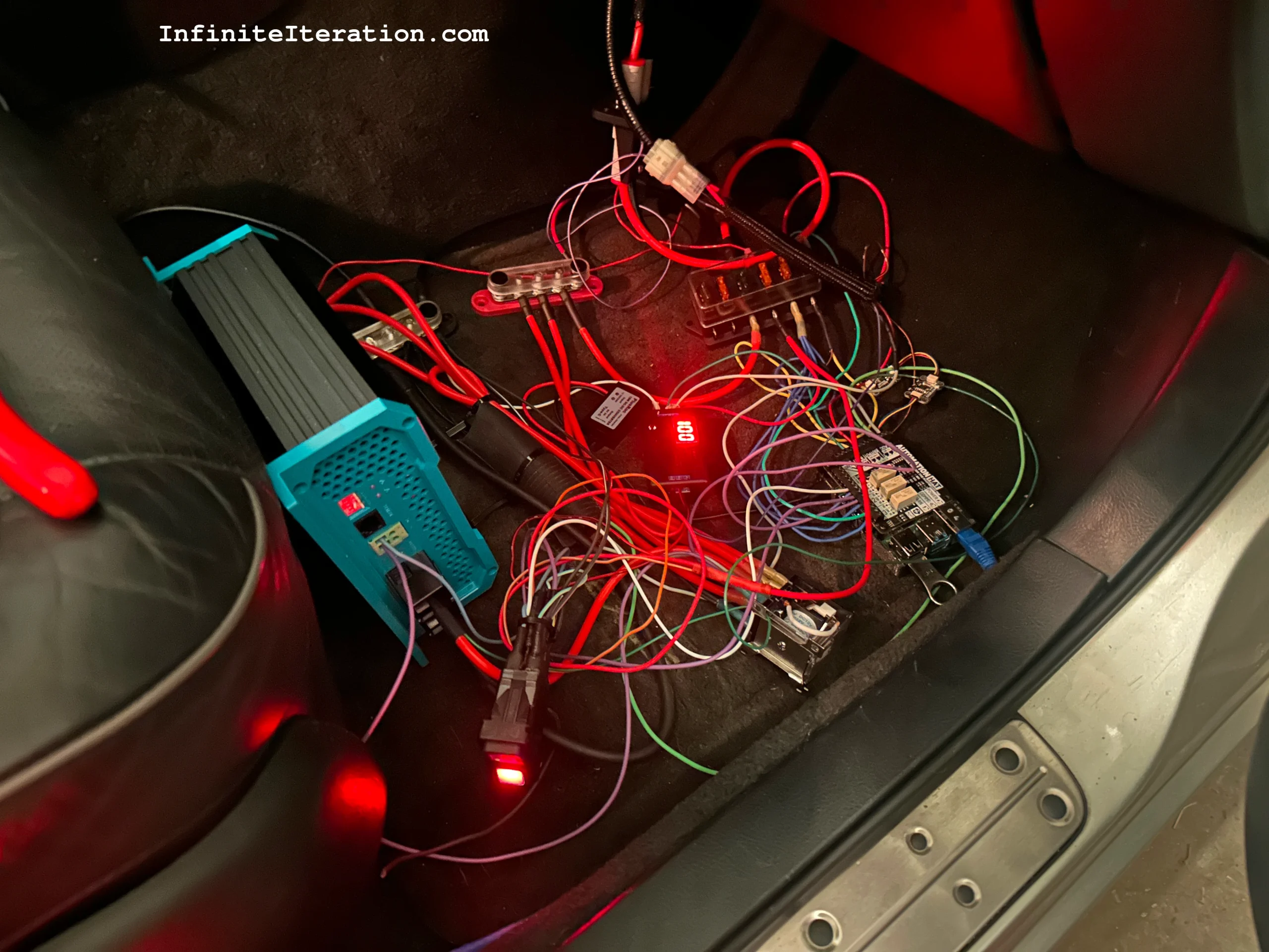
I’ve finished the prototyping/proof-of-concept phase and am now working on the permanent component layout and packaging so the system will look less…like this.
[page still under construction]